Stage 1 - Spine Axle
In this stage you will be assembling the back axle of the Spine that will be holding the Spine box with the motor, electronics and battery.
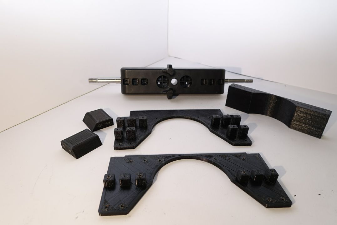
Required Parts:
- Front and Back Enforcements
- Top and Bottom Box Connectors
- Back Axle
- XS and SM Screws
Step 1 - Mount the Top Box Connector
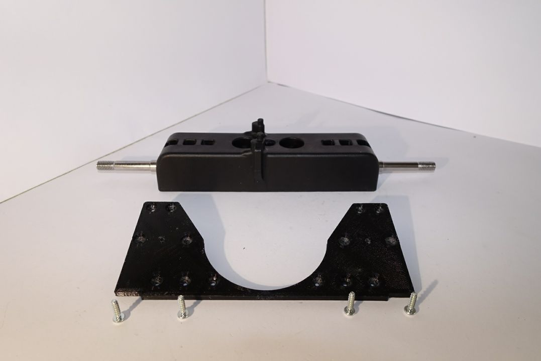
Picture 1.1
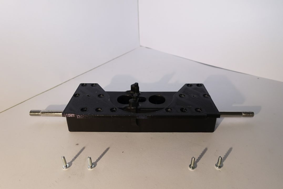
Picture 1.2
Now you will attach the top box connector to the axle. Note that the axle’s top tips need to be to on the left side relatively to the center of the axle as in the picture 1.1. Mount the Top Box Connector onto the axle (picture 1.2).
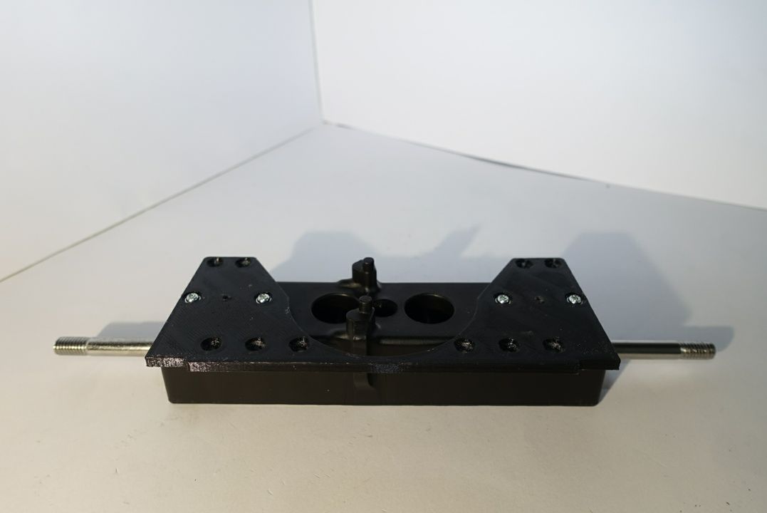
Picture 1.3
Use 4 SM screws to securely attach the elements as shown in picture 1.3.
Step 2 - Mount the Bottom Box Connector
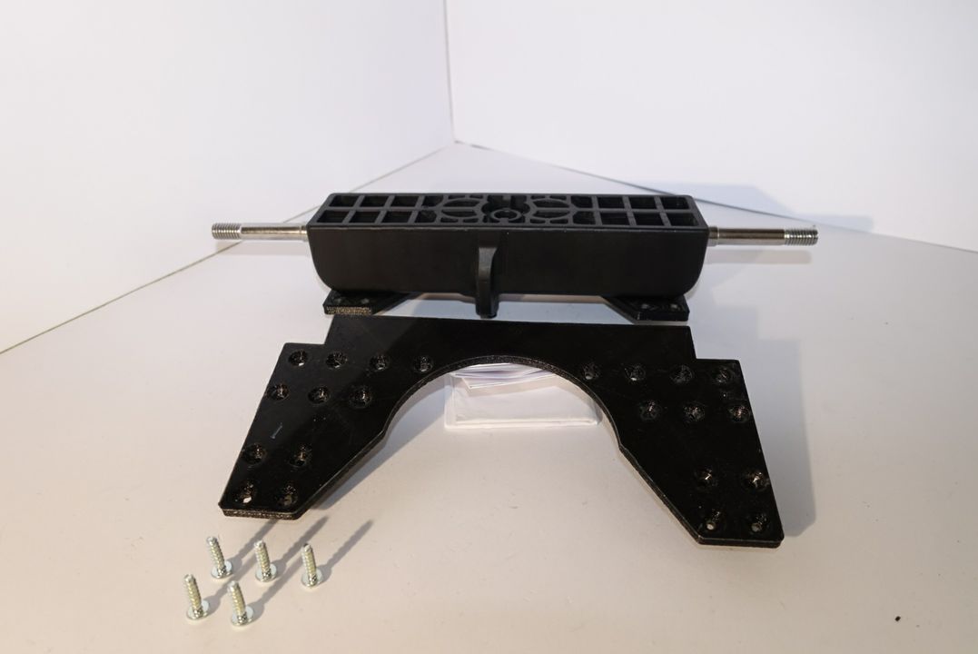
Picture 2.1
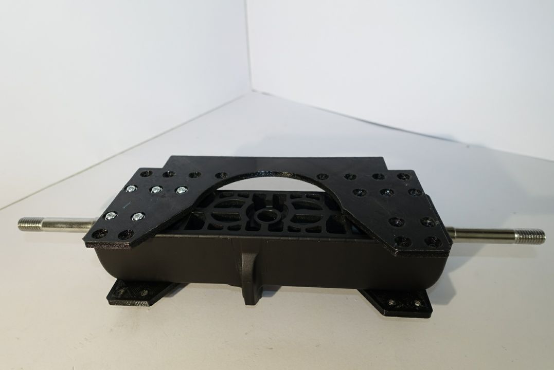
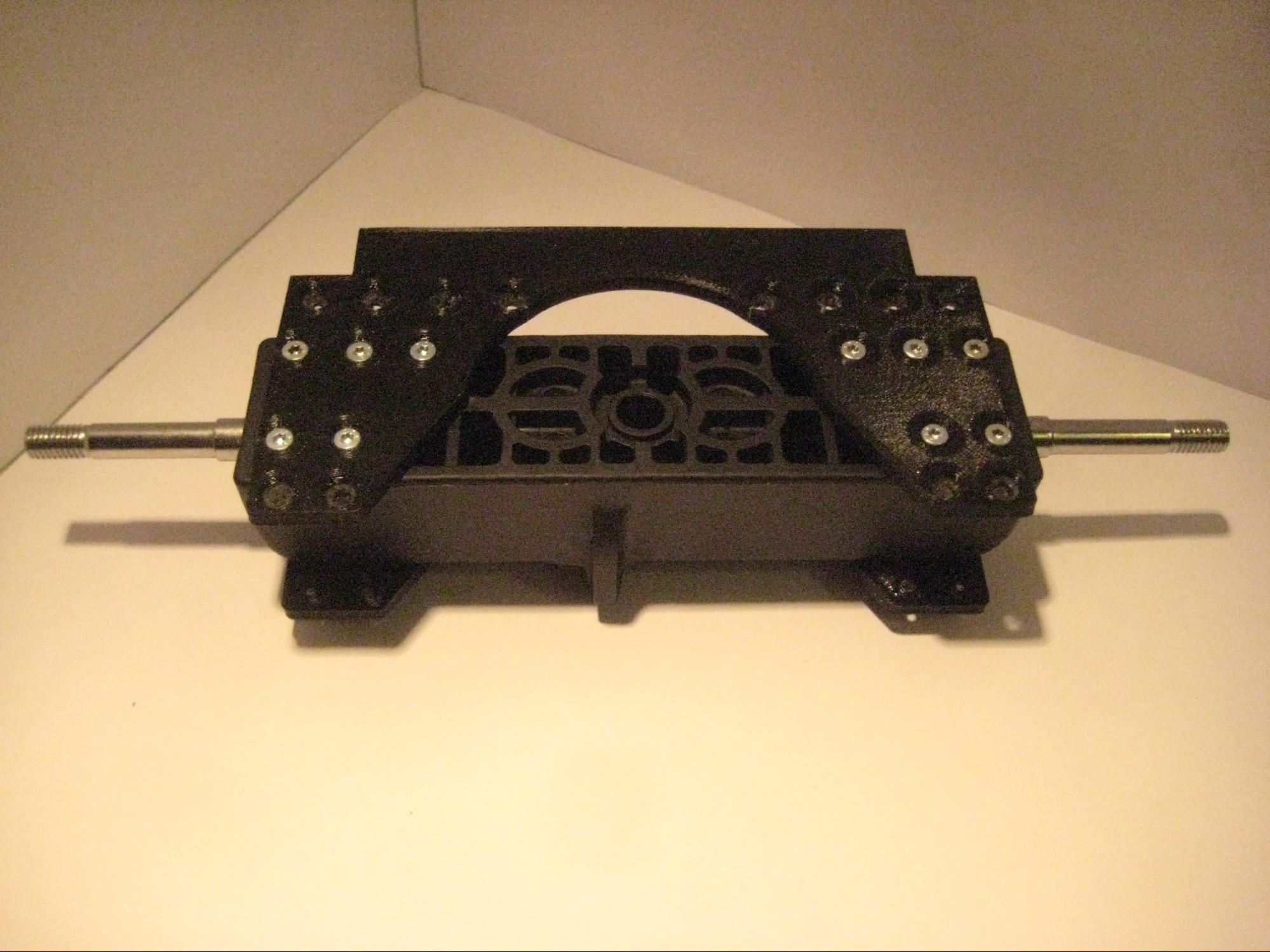
Picture 2.2
In this step you will attach the bottom box connector to the axle (picture 2.1). Just like in step 1 first mount the bottom box connector and then use 10 XS screws to secure the mount as shown in picture 2.2.
Step 3 - Mount the Front Right and Left Enforcements
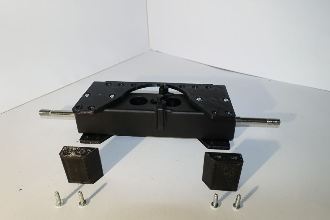
Picture 3.1
Get the front right and left enforcements to and align them according to picture 3.1. Using 4 XS screws fixate the enforcements as shown in picture 3.2 - 3.3.
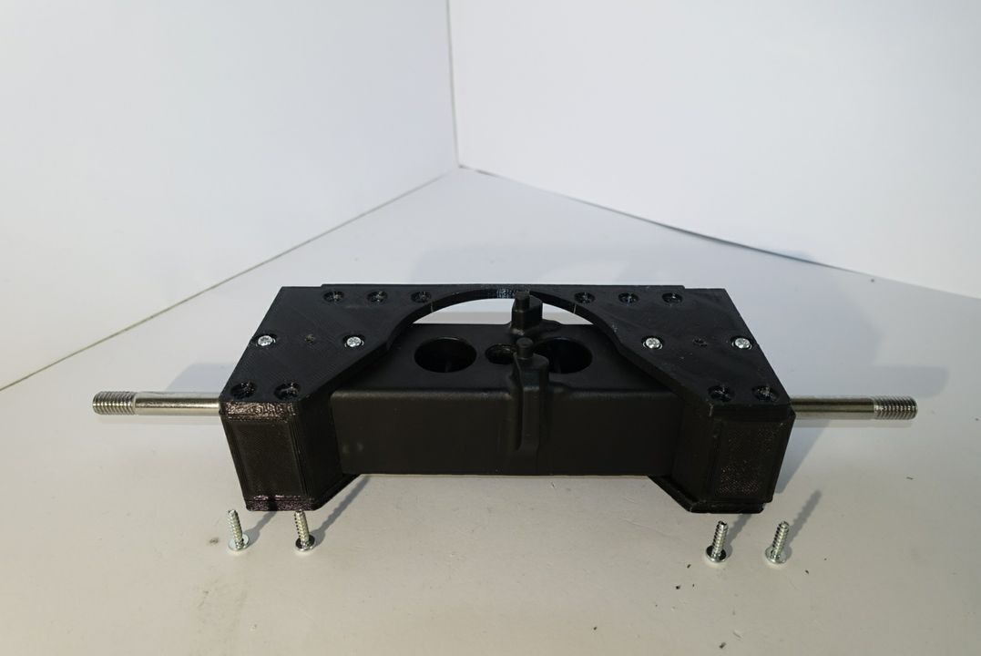
Picture 3.2
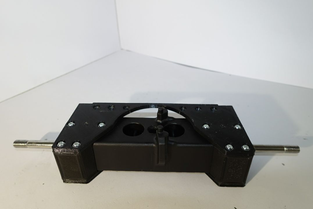
Picture 3.3
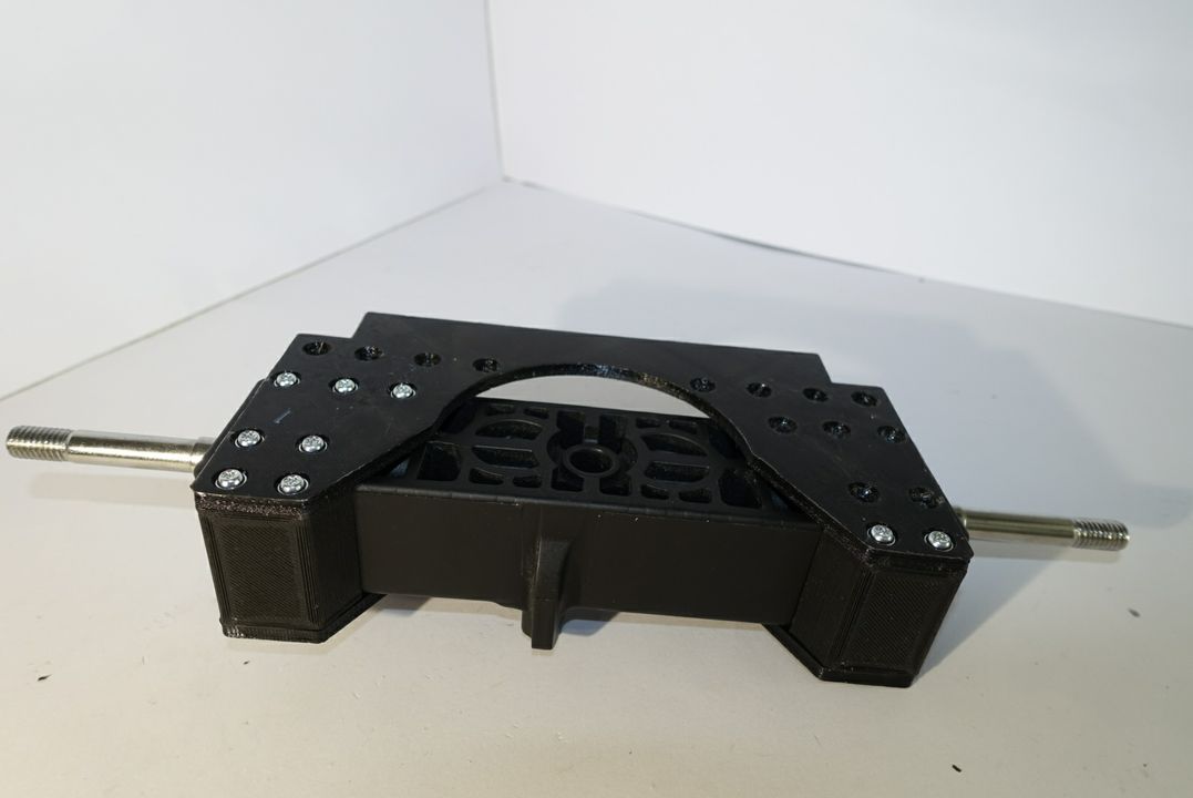
Picture 3.5
Turn the axle upside down and use 4 XS screws to fixate the enforcements from the other side (pricture 3.4).
Step 4 - Mount the Back Enforcement
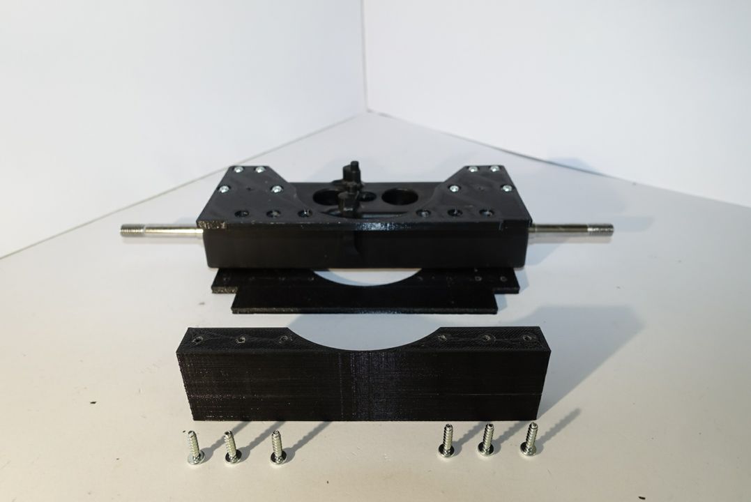
Picture 4.1
Picture 4.2
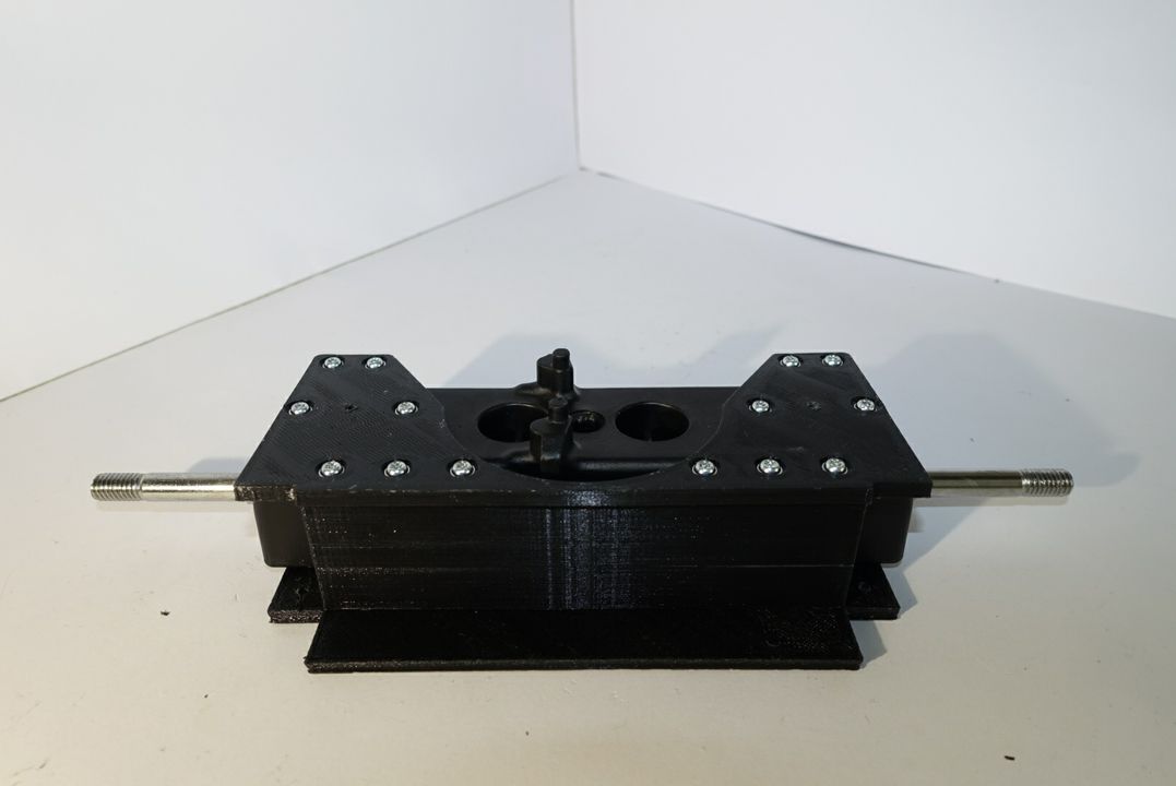
Align the back enforcement according to picture 4.1. As shown in picture 4.2, use 6 XS screws to securely attach the back enforcement to the axle on one side.
Picture 4.3
Picture 4.4
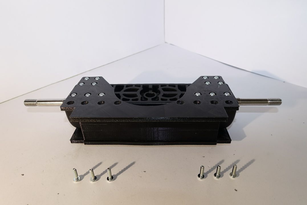
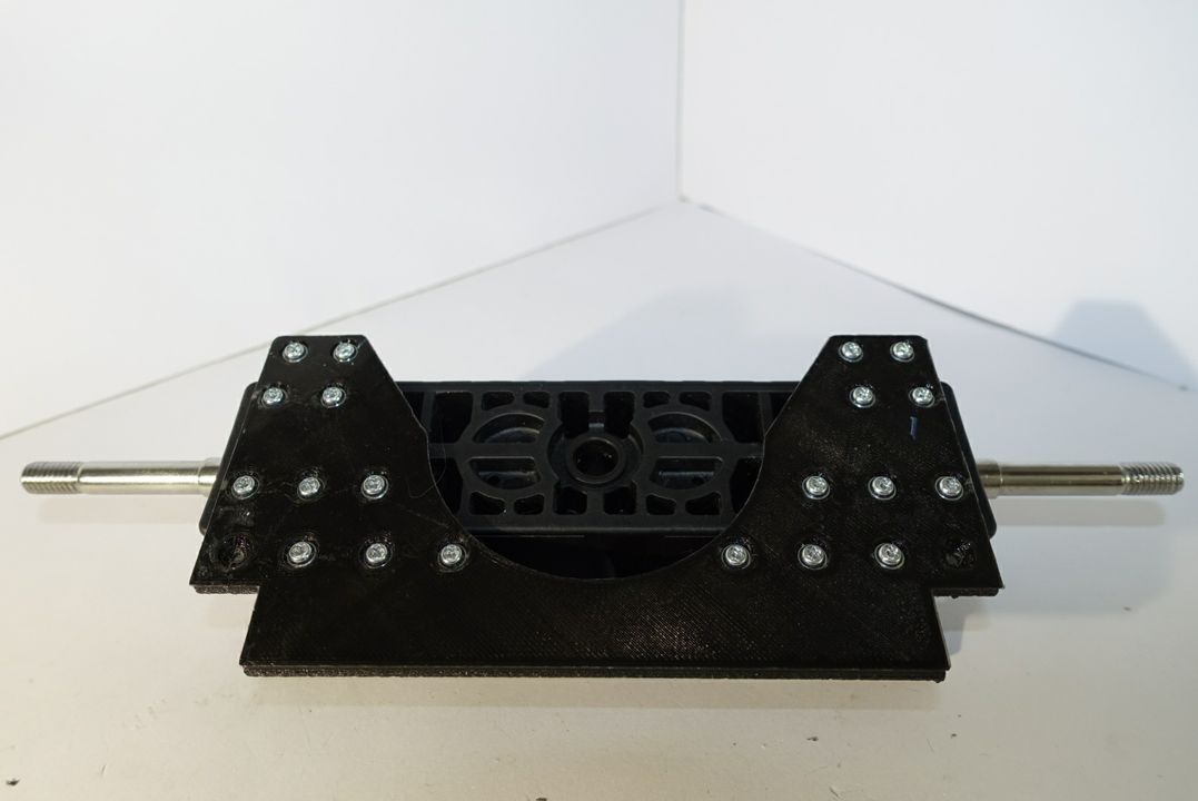
Do the same with 6 more XS screws on the bottom side as shown in picture 4.3 and 4.4.
Updated less than a minute ago
