Stage 2 - Electronics Box
In this step you will assemble the electronics box, containing the motor controller, Wi-F receiver & fuse.
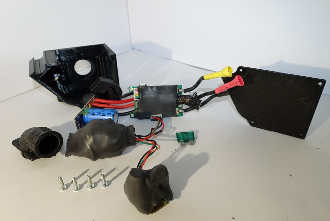
Required parts:
- 1 Cable Protector
- Electronics Box
- Electronics Box Lid
- 6 XS Screw
Step 1 - Mount the Electronics In The Appropriate Sockets
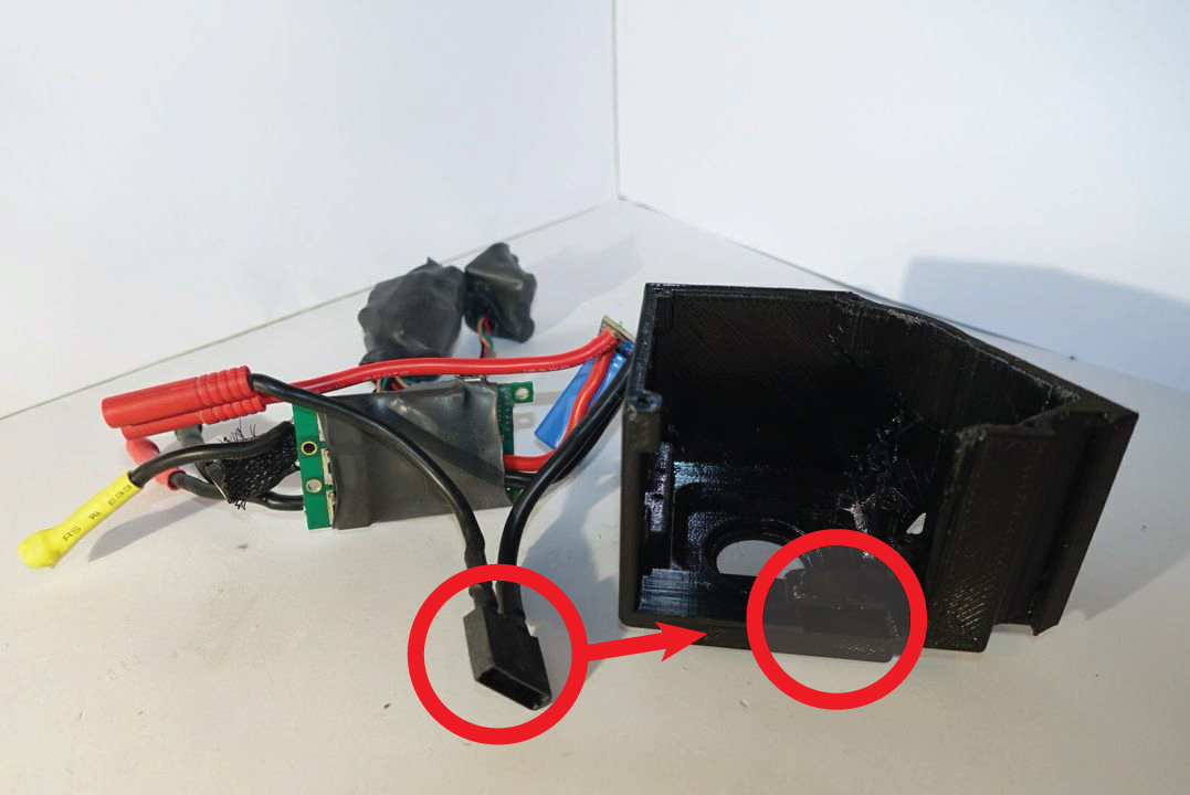
Picture 1.1
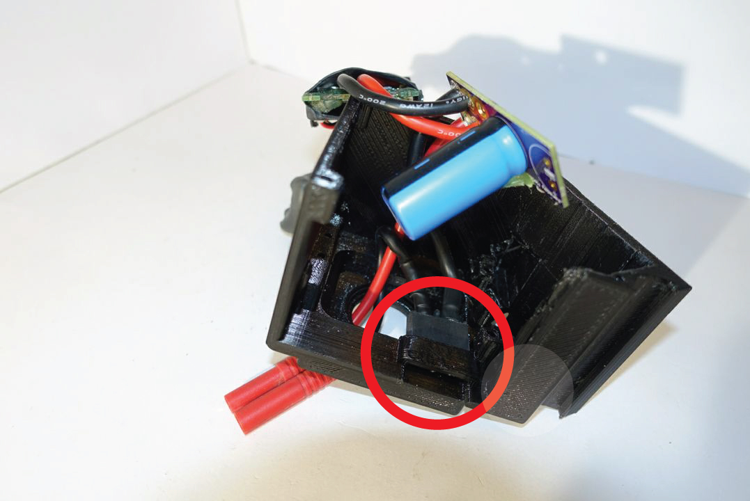
Picture 1.2
First place the battery connector cable through the electronics box hole. Now using picture 1.1 and 1.2 as an example mount the fuse socket into the plastic compartment inside the electronics box. It should slide up the plastic compartment. Upon it being inside the compartment push the end with cables coming out down of the fuse socket down until it clicks. The click will signify that the fuse socket is firmly fixated.
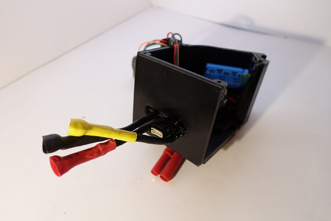
Picture 1.3
Use picture 1.4 identify the top of side of the motor controller (the largest electronics board enclosed in heat-shrink). Now push the 3 color coded cables and the motor sensor cable through the narrow opening of the electronics box. The cables should look the same as in picture 1.3.
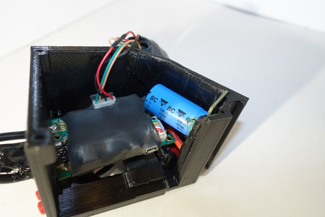
Picture 1.4
Now slide the capacitor board on the right side of the inner electronics box just like in picture 1.4. This action should be done concomitantly with pushing the motorcontroller downwards.
NOTE: Under the capacitor there are three slots for securing the cables. In the middle slot you should place the cables connecting the motorcontroller to the fuse socket. The other two cables should go on the sides of the slots.
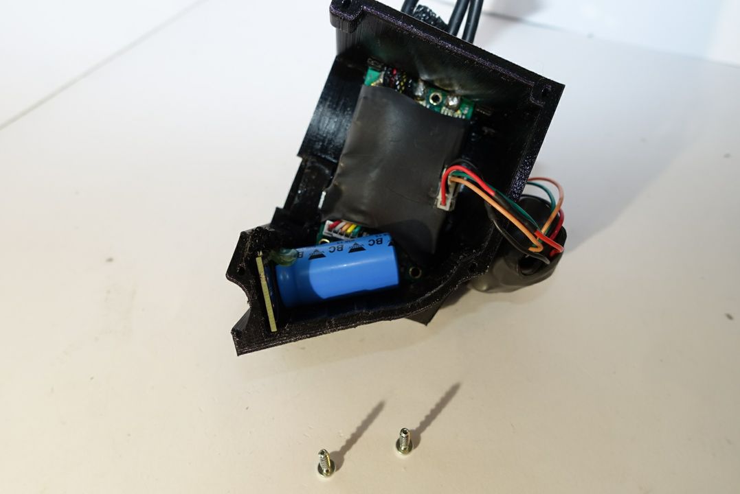
Picture 1.5
Now that the fuse and the capacitor board are well fixated, prepare 2 XS screws, that will be used to fixate the motor controller. Picture 1.5 shows how the all the electronics should look like before using the screws.
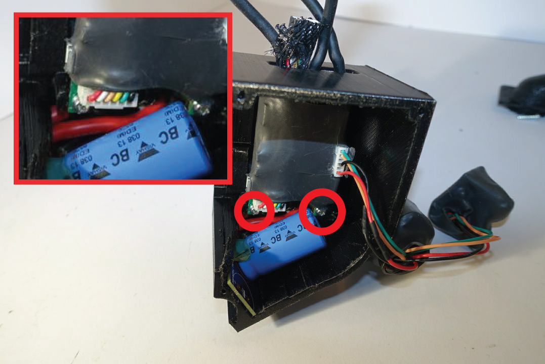
Picture 1.6
Use a screw driver to carefully screw the motor controller onto the electronics box.
NOTE: Make sure that the screws or other parts don't bite any cables. Damaged cables could cause shortages that could damage the electronics.
Step 2 - Assemble the Electronics Box
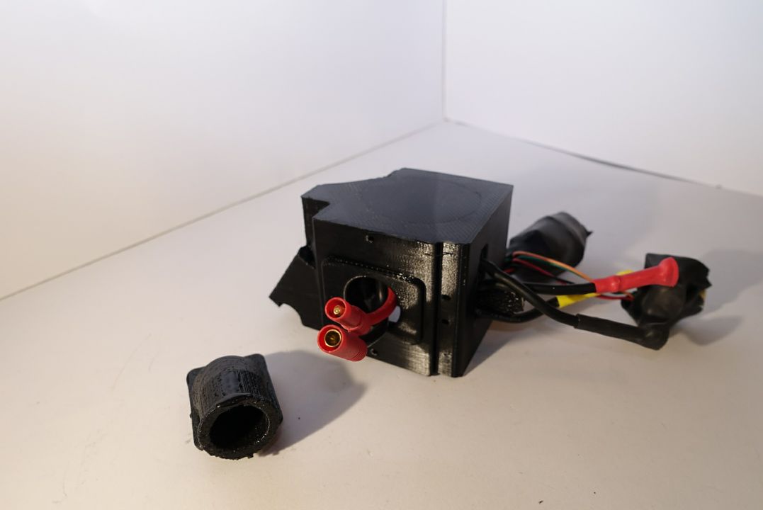
Picture 2.1
Picture 2.2
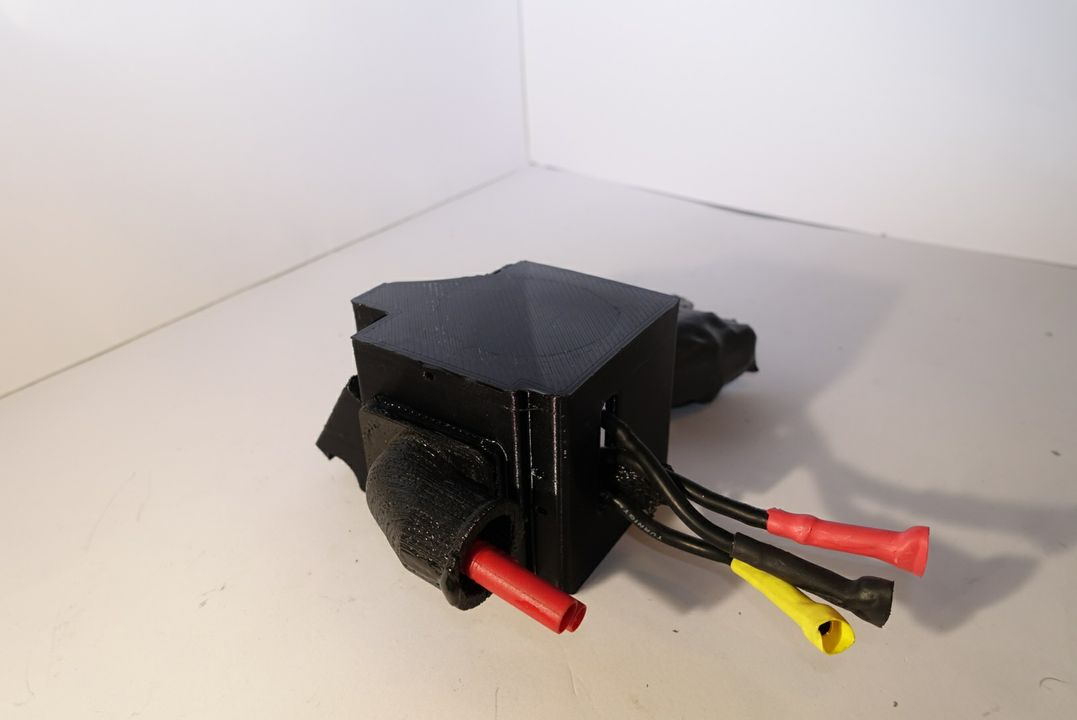
Use picture 2.1 and 2.2 to see how the mounted cable protector should look. It sometimes is quite tricky to get the battery connector through the cable protector. We advise using some adhesive such as liquid silicone to ease this process. Once the battery connector has been inserted through the cable protector, you will have to mount the cable protector onto the electronics box. Push the "lips" of the cable protector inside the electronics box round hole.
Picture 2.3
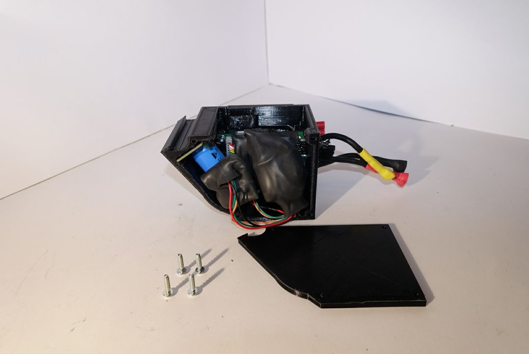
Now that the motor controller is securely mounted, add any other electronics into the electronics box as shown in picture 2.3. We advise that you use a zip tie to wrap around the motorcontroller and the other loose electronics such as your NodeMCU or WeMos.
Picture 2.4
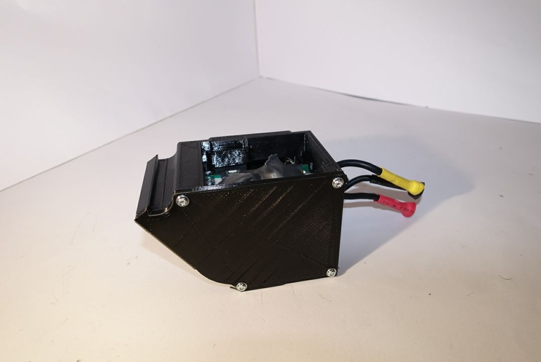
Finally use 4 XS screws to mount the electronics box lid as shown in pictures 2.3 - 2.4.
Step 3 - Insert the Fuse into the Fuse Socket
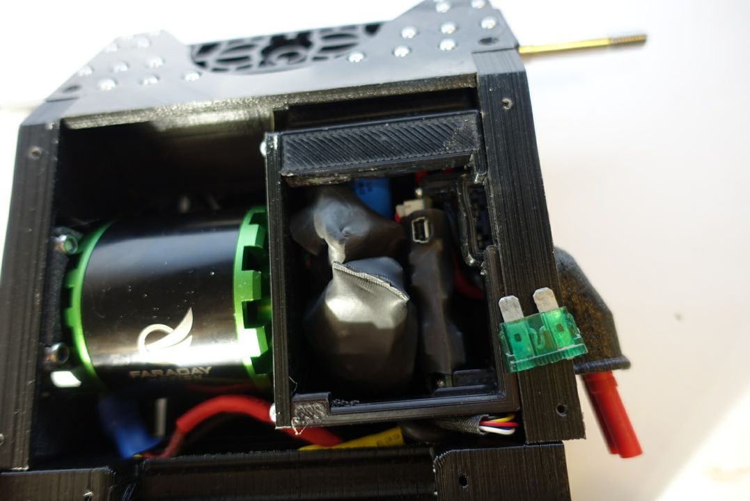
Using pictures 3.1 and 3.2 as a reference mount your fuse into the fuse socket of the electronics box.
Picture 3.1
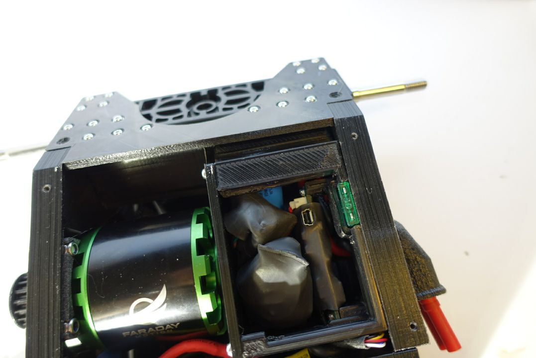
Picture 3.2
Updated less than a minute ago
